
This article was initially published in the ARRL’s Antenna Compendium volume 1, published in 1985 and was recently added to Archive.Org.
By Roy W. Lewallen,* W7E
*5470 SW 152nd Ave., Beaverton, OR 97007
I’ve always been a bit bothered by baluns, since I was never sure what they are supposed to do, let alone how they might go about doing it. The majority of articles deal with various ways of building and testing baluns, of the advantages of one type over another, but almost never a word about when or why a balun is necessary, if at all. Like most amateurs there have been few occasions when I have been able to tell if a balun has any effect on an antenna system, and when it has, the effect isn’t always been good! The turning point came when I was trying to measure the resonant frequency of a folded dipole through a one-wavelength coaxial line. The bridge null varied a great deal as I moved my hand around the coaxial cable, or if the line or bridge was moved. A hastily constructed balun installed at the center of the dipole eliminated the problem. But why?
I found brief, but clear explanation of one phenomenon involved in a paper by Maxwell, W2DU.\1 However, many questions remained. This led me to an investigation of just how baluns are supposed to work, and what problems they are supposed to cure. One surprising conclusion I found from my research is that one popular type of balun, when properly designed and used in an antenna system, may not solve the problems that baluns are expected to solve. Other results indicated that the type of feed line (balanced or unbalanced) has little to do with how well a system Is balanced. In order to verify, or refute, the theoretical results, several experiments were carefully set up and run, and the data was analyzed. The result is a much clearer view of the operation of baluns in antenna systems, and some definite “dos” and “don’ts” regarding their use.
What Problems are Baluns Supposed to Solve?
Baluns usually solve problems caused by an imbalance. An imbalance of what? To answer this question, we need to look at current flow in transmission lines.
In a coaxial cable, the currents on the inner conductor and the inside of the shield are equal and opposite. This is because the fields from the two currents are confined to the same space.\2 With the presence of skin effect, a different current flows on the outside of the shield than on the inside.\3 The current on the outside, if significant, causes the feed line to act like an antenna, radiating a field that Is proportional to this current.
A twin-lead feed line has similar properties, despite its different physical nature. Since it is physically symmetrical, if the currents flowing through the conductors are equal and opposite, the radiation from the line is minimal (assuming that the conductor spacing is very small relative to a wavelength). However, several factors may cause the currents in the two conductors to be imbalanced, that is, other, than equal and opposite. If this happens; the balanced feed line will radiate like a coaxial cable that has current on the outside of the shield. This occurs because the components of the currents on the two conductors that are equal and opposite create fields which cancel. But the field from any remaining component on either conductor (called a common-mode, secondary-mode, or antenna current) will cause radiation.\4,\5,\6 In this article, the current on the outside of the coaxial shield, or the antenna current on the twin lead, will be called the imbalance current: They are caused by the same things and produce the same things and produce the same effects.
Imbalance current, on either kind of line, is the cause of a number of undesirable effects:
- pattern distortion (caused by the feed-line radiation adding to the antenna-radiated field, or by unequal currents in the antenna halves)
- TVI (radiation from a feed line coupling into nearby television sets, house wiring, and so on)
- RF in the shack (caused by a “hot” radiator — the feed line — residing in the shack)
If you have read other articles on baluns you’ll recognize these as the problems baluns are supposed to solve. What isn’t usually too clear is that they are all caused by current imbalance, on either coaxial or twin-lead feed line. Of course, if the imbalance current is sufficiently small to begin with, a balun is not necessary at all. Or it can be said that a properly designed balun will not solve the problem being experienced.
What Causes System Imbalance?
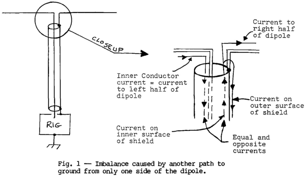
The first cause of imbalance currents was explained by Maxwell. It will be repeated here for completeness. When a balanced antenna is fed with coaxial cable (Fig. 1) the outside of the shield appears as an extra, separate conductor connected to the right side of the antenna at the feed point. The current in the cable’s center conductor flows into the left half of the dipole. The equal and opposite current on the inside of the shield flows partly into the right half of the dipole, and partly along the outside of the shield. The proportion of current which flows each way is determined by the relative impedances of the two paths. The current on the outside is the greatest when the total effective length of the path along the outside of the coaxial cable from the antenna to ground is an integral number of half wavelength, since this makes the impedance presented by the undesirable path relatively low. If the rig ls effectively an odd number of quarter wavelengths from actual ground, it is at voltage maximum and can be hot. On the other hand, there can be other combinations of length for which the imbalance current” will be negligible – cases where a balun does not make any noticeable difference.
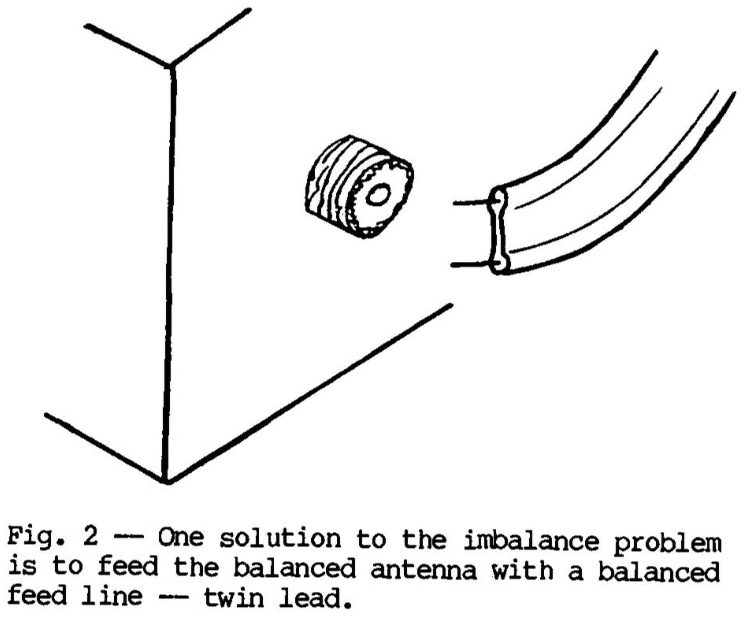
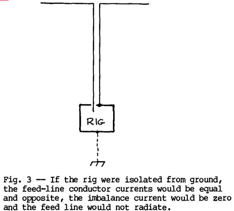
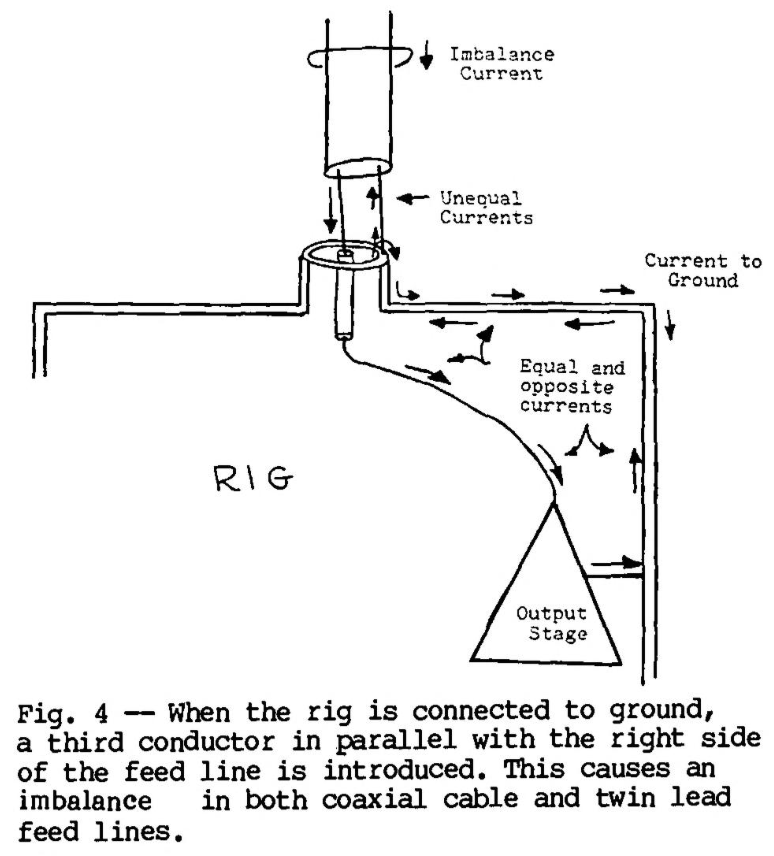
The obvious solution to this problem is to feed the balanced antenna with a balanced feed line — twin lead. This solves the problem neatly, until you encounter the problem which most of us have today, illustrated in Fig. 2. Suppose that we went ahead and connected the line as shown schematically in Fig. 3. If the rig could be totally isolated from ground, the feed-line conductor currents would be equal and opposite, just as they would be if coaxial cable were used; the imbalance current would be zero, and the feed line, and the would not radiate.\7 However, when we connect the rig to ground, as shown by the broken line, we’ve again provided a third conductor in parallel with the right side of the feed line, and the same problem occurs as with the coaxial cable. (See Fig. 4) So either type of line is unbalanced if direct path to ground is provided from one side, and both can be balanced, non-radiating line if the imbalance current is eliminated.
Imbalance current can be caused also by situations where the two sides of the antenna are not precisely symmetrical: Coupling to nearby objects, the tilt relative to ground, or slight differences in lengths of the two antenna halves.\8 Another cause of imbalance currents is induction. If the feed line is not exactly placed at a right angle to the antenna, a net current is induced into it by the antenna field. This current appears as an imbalance current. At UHF, where the diameter of coaxial cable is a substantial fraction of the length of the antenna elements, coaxial line is more difficult to place symmetrically relative to the antenna than twin lead is (this is sometimes given as the only reason for using a balun!). The problem is negligible at VHF (except perhaps with very large diameter coaxial cable) or below.
What Baluns Do
Let’s recall what we want a balun to do: cause the currents in the feed-line conductors to be equal in magnitude and opposite in phase, resulting in a zero imbalance current. How well do the popular balun types do this?
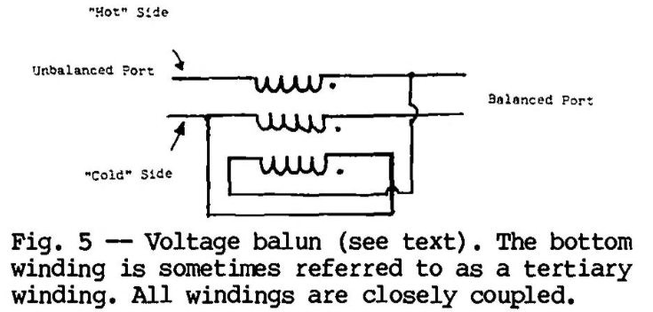
One type of balun is known as transformer-type balun or balun with a tertiary winding (Fig.
5).\9 This type is commonly used for providing single-ended to differential conversion for driving balanced mixers; push-pull amplifiers, and so, on it seems to be suitable for our purpose. An analysis of its operation (see Appendix 1) shows that it does indeed perform an unbalanced-to-balanced conversion. The voltages at the balanced port are caused to be equal, and opposite, in phase relative to the cold side of the unbalanced port. Thus, the use of this sort of balun will eliminate the problem of current flow on the outside of line only if the antenna is perfectly balanced. There is nothing gained by forcing the voltages of the two antenna halves, whether balanced or not, to be equal and opposite relative to the cold side of the balun input (usually connected to the shield of a coaxial feed line), since the antenna field is proportional the currents in the elements, not the voltages at the feed point. I will call this type of balun a voltage balun to emphasize that it balances the output voltages regardless of load impedances.
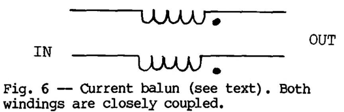
Another type of balun that appears in the literature has been called a choke-type balun (Fig. 6).\10 It resembles the voltage balun, except that the tertiary winding is missing. The analysis of both types of balun in Appendix 1 shows that the effect of a tertiary winding is not a minor one. The two types of balun produce fundamentally different results. The voltage balun causes equal and opposite voltages to appear at the balanced port regardless of load impedances, but the second type of balun causes equal and opposite currents on the conductors at both ports for any load impedances. For this reason, I will call this type of balun a current balun. Intuitively, the current balun produces the sort of effect we would expect. When wound with twisted pair or twin lead, it is nothing but a bifilar RF choke that impedes any net current which tries to flow through it. When wound with coaxial cable, it can be visualized as an RF choke acting only on the outside of the coaxial-cable shield, reducing the current to a very small value. This is the exact function a balun needs to accomplish when used in an antenna system.
A current balun can be constructed by winding coaxial feed line into a coil, winding either type of feed line onto core, or by stringing ferrite cores along either type of line.\11 Even if the balun is mediocre, there will be no effect on the desired properties of the line itself (impedance, electrical length, SWR, and so on). A less-than-perfect voltage balun can have a profound effect on the impedance seen at its input because of the tertiary winding. Impedance-transforming (4:1) baluns are discussed in Appendix 3.
Experiments
A series of experiments was designed to test the validity of the results of the theoretical investigation. A 10-meter dipole was set about 12 feet above the ground, and about five feet above the edge of an elevated wooden deck (Fig. 7). One-half wavelength from the center of the dipole, a 4-foot rod was driven into the ground, which was completely saturated with water at the time the experiments were run (during November, in Oregon). To further lower ground-system impedance, six radials were placed on the ground around the ground rod. Two feed lines were cut to a half wavelength: one of RG-59/U coaxial cable, and one of 72-ohm transmitting twin lead. The velocity factors of the cables were not taken into account, since the intent was to have the outside of the coaxial cable, or the two parallel conductors of the twin lead, be an electrical half-wavelength long. A low-power 10-meter transmitter located, and connected to, the ground system was used as signal source.
Current probes and baluns were built as described in Appendix 2. Two of the current probes were permanently wired into each side of the dipole near the feed point, and a third was used for all feed-line measurements. A single detector was used for all measurements, and it was calibrated over the range of encountered output levels by using a signal source and precision attenuator. The results of the experiment have been corrected to account for measured nonlinearity of the detector.
No attempt was made to keep the power level or impedance match constant from one test to another. When running an experiment with no balun, a current balun, and a voltage balun the only variation in the system was to change the balun. Initially, the intent was to use the antenna current probe readings as a measure of current balance in the antenna halves. However, a case was encountered in which the antenna halves showed equal currents, but a large imbalance current was measured in the feed line at the antenna feed – a seemingly impossible combination! (The equal antenna currents were even more suspicious because no balun was being used, and the antenna had intentionally been made nonsymmetrical for that test.) A bit of thought provided the answer. The imbalance current is measured by placing the feed line through the current-probe toroid. In conjunction with the detector, it measures the magnitude of the vector sum of all currents flowing through the toroid. Each antenna current probe, with the detector, ‘measures the magnitude of the current in each half of the antenna, at the feed point. What must be happening is that the currents in the dipole halves are equal but not 180 degrees out of phase. A check of the currant-probe outputs with a good-quality dual-channel oscilloscope confirmed the hypothesis: The currents were 230 degrees, rather than 180 degrees, apart, although equal in magnitude. What an interesting pattern that dipole would have! But this illustrates how misleading the magnitudes of element currents can be when judging balance. Measuring the imbalance current in the feed line at the feed point does, however, provide a good indication of the balance of the currents in the antenna halves. If the imbalance current is very small, the currents in the sides of the antenna must be nearly equal in magnitude and opposite in phase. A significant imbalance current, on the other hand, indicates that one or both conditions have not been met.
Measurement of the imbalance current on the feed line also indicates how much the feed line will radiate. The imbalance current at the rig provides a measure of RF in the shack. In the following tests, the magnitude of the current was measured in each conductor, then the magnitude of the imbalance current was measured by placing the complete feed line through the current-probe toroid. A single figure of merit, balance, was calculated as:

Experiments 1 through 4 were done using a nominally symmetrical dipole, although results indicate that some asymmetry was present. For experiments 5 through 7, the dipole was intentionally made nonsymmetrical by lengthening one side by five inches, and shortening the other side by the same amount.
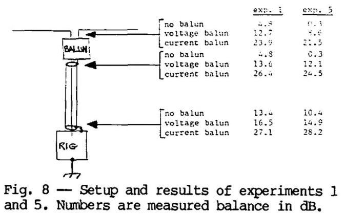
Experiments 1 and 5:
See Fig. 8. The dipole was symmetrical for experiment 1, nonsymmetrical for experiment 5.

Discussion
If the dipole balance (symmetry) were indeed perfect for experiment 1, we would expect the currents in the sides of the dipole to be unbalanced, resulting in imbalance current on the feed line. This is because the outside of the coaxial shield appears as a conductor in parallel with half of the dipole. Also, either a current or voltage balun should reduce the imbalance current to zero. Since the feed line is placed symmetrically relative to the antenna, no additional current should be induced into the feed line, so the imbalance should also be quite small at the rig end of the line when either type of balun is used.
With the nonsymmetrical dipole (experiment 5), we would expect the voltage balun to do worse than In experiment 1. We would also expect the current balun to do about the same, and the no-balun case to be considerably worse.
Results
In experiment 1, the voltage balun did not perform as well as the current balun, indicating some asymmetry In the dipole. At the frequency chosen, the small differences in connections and a slight tilt of the antenna could early account for what happened. When no balun is used, a curious result is a much better balance at the rig end than at the antenna end of the feed line. This may be because the feed lines weren’t exactly an effective half wavelength long, because there was a wire of about six inches in length connecting the rig to the ground system, or because the feed line was doubled back on itself for a short distance near the rig to provide strain relief. Perhaps the doubling back generated enough inductance to cause a current balun or RF choking effect. The better balance at the rig end can be seen in the results of all experiments.
The no-balun result was worse with the nonsymmetrical dipole than the symmetrical one, as expected, and the current balun did about the same in both cases. The voltage balun, although slightly worse with the nonsymmetrical antenna, was better than expected, but still definitely inferior to the current balun.
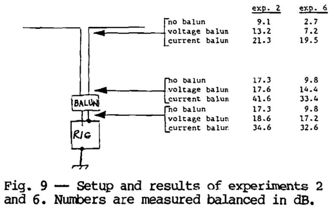
Experiments 2 and 6:
See Fig. 9. The dipole was symmetrical for experiment 2, nonsymmetrical for experiment 6.
Discussion
The results of these experiments should duplicate those of the previous pair since the feed line is placed symmetrically relative to the antenna to avoid induced current. The only difference is that the balun is placed farther down in a symmetrical or nonsymmetrical system.
Results
The trend is clearly the same as in experiments 1 and 5; the current balun provides the best balance, the voltage balun is second best, and a feed line with no balun is the worst case. The balance with no balun was better in this experiment, however, (except at the rig end with the nonsymmetrical antenna, which was about the same), and the balance at the rig end was substantially better when using the current balun. Time did not permit me to run additional experiments to explain these differences but the ability of the current balun to achieve superior balance was again illustrated.
Experiments 3 and 7:
See Fig. 10. The dipole was symmetrical for experiment 3, nonsymmetrical for experiment 7. The voltage balun was connected with the balanced port toward the antenna.
Discussion:
These experiments, and experiment 4 were conducted to test the idea that coaxial cable and twin-lead feed lines would behave in the same fashion, as theorized earlier. If so, the results of
Fig. 10

these experiments should be similar to those of the previous pair.
Results:
With no balun, the results were those of experiments 1 and 5 (the test with no balun was not rerun). With the current balun, the results were similar to those of experiments 2 and 6, indicating that coaxial cable can be used as a balanced feed line (in the sense discussed earlier) with a balanced or somewhat-unbalanced load. This data also points to the possibility that a current balun could be added to an existing antenna system at the rig end of the line, with results similar to those obtained by placing it at the antenna, in some cases at least. This would certainly be worth a try in systems where the symptoms indicate the need for a balun, but the antenna itself is difficult to get to. With the symmetrical antenna, the voltage balun made balance worse at both ends of the feed line than no balun at all. The balanced port of the voltage balun sees two unequal impedances to ground: the coaxial center conductor, ending in one dipole half, and the coaxial shield terminating in the other. The shield is capable of radiating but the inner conductor isn’t, and the two are of different diameters, accounting for the different impedances. The voltage balun predictably generates unequal currents in the different impedances, causing additional current imbalance. A voltage balun was not evaluated in this application with a non-symmetrical dipole, having shown distinctly inferior results even with a symmetrical one.
Experiment 4:
See Fig. 11. The dipole was symmetrical. The voltage balun was connected with the balanced port toward the antenna.
Discussion:
Like experiments 3 and 7, this was intended to test the similarity between the performance of the two kinds of feed line, provided that all other conditions and connections are the same. If the two feed lines act the same, the results should duplicate those of experiment 1.
Results:
The current balun again causes the predicted results, except it shows improved performance at the rig over experiment 1. In contest, the voltage balun gave strikingly poorer balance at the antenna, and markedly poorer performance at the antenna end of the feed line, compared to no balun at all. If the antenna were completely symmetrical, there should be no current imbalance at the input end of
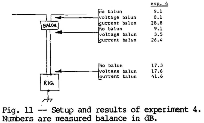
the voltage balun, but with the moderate (unintentional) imbalance presented by the actual antenna, the current balance on the feed line was seriously degraded. This configuration isn’t likely to be used in actual practice, but helps illustrate the operation of the baluns and feed lines.
Conclusions
Although some aspects of the experimental results remain to be explained (as they always will be unless performed under extremely controlled conditions), they certainly support the theoretical analysis. The current balun gave superior balance at every measured point in each experiment. The voltage balun improved balance in most cases, explaining its acceptance in spite of the theoretically and experimentally demonstrated superiority of the current balun to cure the problems we have discussed. As always, finding the answers to questions generates yet more questions. Lack of time did not permit experiments with the feed line placed non-symmetrically with respect to the antenna, to induce imbalance current into the feed line. The results of such an experiment should be interesting, and enlightening.
Is there an optimum point in the feed line to place a balun? Suppose the effective stance along the feed line/ground wire from the antenna to ground is an integral number of half wavelengths, and the balun is placed a quarter wavelength below the antenna as sometimes recommended. Wouldn’t the imbalance current be conducted as before?” Would induced current, if present, be reduced? What’s the effect of poor coaxial shield coverage?
More work needs to. be done I evaluating the various styles of current baluns (such as coaxial cable wound into a choke, coaxial cable wound on a ferrite or powdered iron core, insertion of the feed line through one or more ferrite cores, and so on) for their primary characteristic: causing currents to be equal in magnitude and out of phase. The method I’ve used is briefly described in Appendix 2, but how good is good enough?
The basic investigation reported here does answer some of the major questions regarding baluns. I now know what symptoms I can expect a balun to cure, why it will (or won’t!) cure them, how to predict and measure the balun’s success in doing so, and what type of balun to use. I hope you do too!
Appendix 1: A Brief Analysis of Balun Operation
Analysis of both balun types assumes “ideal” operation: All flux is linked to all windings (coefficient of coupling is one), and each winding has sufficient self-impedance to make the magnetizing current negligible.

The Voltage Balun
Because of transformer action, V1 – Y3 = V2 – V0 = V0 – V1. The third term comes about because of the “tertiary” winding shown at the bottom. Rearranging the last two terms, V2 – V0 = – (V1 – V0). So relative to V0 (the voltage at the cold side of the unbalanced port), the voltages at the balanced port are equal and opposite.
The current It flowing in the tertiary winding is, by inspection, -(Ii + I0 – I2) and also (Ic – I1), so -(Ii + I0 – I2) = (Ic – I1). Because of the property of coaxial cable discussed in the body of the article, Ii = -Ic, so Ic – I0 + I2 = Ic – I1; thus I0 = I1 + I2, So for the current on the outside of the shield, I0, to be zero, load currents I1 and I2 must be equal and opposite. Since V1 and V2 are forced to be equal and opposite relative to V0, the only way for I1 and I2 to fulfill this requirement is for the impedances from each side of the balanced port to the cold side of the unbalanced port to be equal. Thus, only a perfectly balanced load will cause no current on the outside of the coaxial cable. Ironically, if this does occur, current It = 0, and the tertiary winding accomplishes no function.
The Current Balun
In an ideal transformer of two windings having an equal number of turns, the currents in the windings are forced to be equal and opposite. So IC = – ( Ii + Io ). Again, Ii = -lc, so Ic = lc – Io, resulting in Io = 0. This result is independent of the load impedances. And, since the load currents are the winding currents they are also equal in magnitude and opposite in phase.
If the balun is constructed by winding coaxial cable on a core or into an air-core coil, or by stringing ferrite beads on the outside, the operation can be understood by observing that the inside of the coaxial cable “can’t tell” what’s going on outside. The currents on the inside – equal and opposite happen regardless of the outside environment, but the construction causes a high impedance to current flow on the outside, acting like a choke to the imbalance current (hence the appropriate name choke balun). When constructed of twisted-pair line, the effect on imbalance current is the same and for the same reasons, but operation is more difficult to visualize.

Appendix 2: Construction and Test of Baluns, Current Probes and Detector
Voltage Balun
The voltage balun was constructed using the method described in Ref. 8. A piece of no. 26 wire was laid along a length of RG-178/U cable (small-diameter Teflon-insulated coaxial cable), and heat-shrinkable tubing, was applied over the assembly. The modified cable was wound on an FT82-61 core using ten turns. This construction method was decided on after trying to wind a balun with two pieces of coaxial cable in bifilar fashion, the shield of the second being contacted as the tertiary winding. The latter construction method was much poorer in proving good voltage balance.
Voltage balance was evaluated by connecting the cold side of the unbalanced port to a ground plane and the balanced port to two resistors of unequal value, the other ends of which were connected to the same point on the ground plane. Using resistors of 27 and 54 ohms, the ratios of voltages appearing at the two resistors were measured as about 3/4 and 1-1/2 dB, depending on which resistor was connected to which lead of the balanced output.
Current Balun
The current balun consisted of 15 turns of RG-178/U coaxial cable on an FT82-61 core. Performance was evaluated by connecting the output end to 27 and 54-ohm resistors to ground, and measuring the voltages across them. A properly working current balun should generate twice the voltage across the 54-ohm resistor than across the 27-ohm resistor, regardless of which lead is connected to each resistor. The results were within 0.2 dB of theoretical, with either lead connected to either resistor.
Current Probe
The current probes were constructed as shown in Fig. 12. The output voltage equals ten times the current, in amperes, being measured. Insertion resistance is one ohm.

Detector
The detector is shown in Fig. 13. It was calibrated using a signal source and precision attenuators, at the operating frequency. Calibration using a dc source was found to be inaccurate.

Appendix 3: Impedance-Transforming (4:1) Baluns
The common 4:1 balun, shown schematically in Fig. A3-1, is a voltage balun. If used with a current balun as in Fig. A3-2, the combination acts like a 4:1 current balun. Or it can be converted to a 4:1 transforming current balun by adding a third winding, as shown in Fig. A3-3. A 1:1 voltage balun could be converted to a 4:1 current balun by reconnecting the existing windings. The difficulty with using this configuration is that, like the 1:1 voltage balun, all windings must be closely coupled, and rather severe impedance changes can occur because of transformer imperfections.
A better approach is shown in Fig. A3-4. Old-timers will recognize this as the configuration used by the balun coils commonly used some years ago. This balun does force equal and opposite currents at the input and output, so it is a true current balun, and it performs a 4:1 impedance transformation. Although it, does require two cores which must not be coupled **, it has several advantages: It’s much easier to tightly couple two conductors than three, it’s much more forgiving than the other configurations, and it lends itself to easy construction. One method is simply to wind coaxial cable on to cores, with the center conductors being the conductors shown on the outsides in the figure. This balun can also be used in all-coaxial-cable systems. Besides effecting a 4:1 impedance transformation, it will greatly reduce any current flowing on the outsides of the lines.
** If ferrite rods or air-core coils are used, don’t place them end to end. Place them side by side and spaced a fair distance, or, better yet, at right angles. Less care needs to be taken with toroidal coils.


References
\1 Maxwell, Walter, W2DU, “Some Aspects of the Balun Problem,” QST, March 1988, p. 38.
\2 If a perfect shield Is assumed (a reasonable approximation for this analysis) the result follows directly from Ampere’s Law. For a more detailed explanation, see Electromagnetic Energy Transmission end Radiation, by Richard B. Adler, Lan Jen Chu, and Robert M. Fano (Wiley, 1960).
\3 A very clear development of the phenomenon of skin effect may be found in Chapter 7 of Electric Transmission Lines by Hugh H. Skilling (McGraw-Hill, 1951).
\4 Winningstad, C. Norman, “Nanosecond Pulse Transformers,” IRE Transactions on Nuclear Science, March 1959.
\5 Matick, Richard E., “Transmission Line Pulse Transformers — Theory and Application,” Proceedings of the IEEE, Vol. 56, No. 1, Jan. 1968.
\6 Hall, Gerald L., K1TD, ed., The ARRL, Antenna Book, 14th ed., Chapter 5, (ARRL, 1982).
\7 ln practice, there is always an RF path from the rig to ground, and its impedance should be made low as possible. The rig should always be grounded for safety.
\8 See Ref. 6.
\9 Nagle, John J., K4KJ, “High-Performance Broadband Balun,” Ham Radio, Feb. 1980, p. 28.
\10 See Ref. 1.
\11 Reisert Joe, W1JR, “Simple and Efficient Broadband Balun,” Ham Radio, Sept. 1978, p 12.