
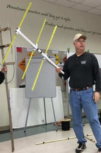
One of the most fun amateur antenna projects is a PVC measuring tape antenna. The flexible measuring tapes make it easy to transport, and the PVC comes apart to make it even easier to carry.
This type of antenna works well for direction finding in games like a fox hunt or when you need just a little more gain to hit the repeater.
This design is an adaptation of the wb2hol tape measure project. Joe’s site has many details regarding the derivation, pattern, and gain properties of this antenna.
In June 2018, SCARS started building these kits. They are available to our members at $10 each. These are available at club meetings or by contacting Mark Kleine.
Materials Needed
These are the parts that are included in the SCARS tape measure kit:
- 6′ WI-FI Extension (SMA) coaxial cable (1) eBay Details (cut off the unneeded connector)
- 3/4″ PVC slip tee connector (1) eBay Details
- 3/4″ PVC slip cross connector (2) eBay Details
- #16 hose clamps (6) eBay Details
- 5″ of 14 gauge solid wire (by the foot at Home Depot)
- 3/4″ PVC schedule 40 pipe – Two 11 1/2″ sections and a 7″ section Home Depot Details
- 1″ wide tape measure 9 1/2′ long (1/2 of a tape) Harbor Freight Details or Harbor Freight Details
- A few tie-wraps to keep the coax held onto the boom
Tools Needed
This kit goes together pretty easily, but the following tools make it happen:
- flat-blade screwdriver or 5/16″ nut driver
- soldering iron, solder, and flux or Vaseline
- sandpaper to rough up the tape measure
Element Lengths
- Director – 35 1/8″
- Driven – 35 1/2″ (cut in half to 17 3/4″ each)
- Reflector – 41 3/8
Building the Antenna
Building the SCARS tape measure antenna is very easy. Once all of the parts have been obtained and cut to length, you’re just a few steps away from getting on the air.
The first step is to mount the long measuring tape, known as the reflector, across one of the PVC crosses. Make sure to center the tape on the cross. Use a pair of hose clamps, and secure them firmly.
Step two is to mount the slightly shorter measuring tape, known as the director, across the PVC tee. Like the first connection, make sure the clamps are firmly attached, and center the tape on the tee.
Step three is to prepare the coax. You have a 6′ SMA extension cable in the kit. Check your radio to see what SMA connector you need to connect. Cut off the end you don’t need, and you’ll have a 6′ connection. You’ll need to strip about 2″ of the outer jacket, as shown below. You’ll also need to strip about 1/4″ off the center insulation. Finally, you’ll need to roll the shield insulation into a wire shape, as shown below.
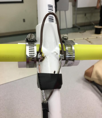
Step four is to solder the coax on to the corners of the two shortest tapes, as shown. We have already stripped off the paint with a buffer wheel and tinned the connection with solder. Bend the 14 gauge wire into a hairpin shape, and solder the coax, the two tapes, and the hairpin connector, as shown.
Step five requires you to mount the driven assembly on the remaining PVC cross, as shown. Make sure that the coax leads in the solder connections are spaced 1″ apart. Use a tie wrap, or black tape, as shown, to secure the coax to the PVC cross.
Step Six, place one of the longer PVC pipes in the top of the driven PVC cross and the short section of PVC pipe in the bottom of the driven PVC cross. Place the shorter, director, PVC tee on the top PVC pipe, and the shorter, reflector, PVC cross on the bottom PVC pipe.
Finally, put the last longer PVC pipe into the tail of the cross. Use this pipe as a handle or a connection to a mounting position.
Your antenna is ready to test! Connect it up to your radio, and point it at your target. Sweep the antenna from right to left, and you should be able to hear a drop in the signal from a remote RF source. Rotate the antenna, and you’ll be able to peak the signal’s polarity.
If you use the antenna portable, you’re ready to go. If you mount this permanently in your attic, create a mounting point, and slide the 3/4″ PVC pipe into the bottom of the reflector PVC cross. You may glue the PVC for a permanent installation. Or, hang it with string from the rafters.